A series rlc circuit has a 200 khz resonance frequency – A series RLC circuit with a 200 kHz resonance frequency presents a fascinating case study in circuit analysis, where inductance, capacitance, and resistance intertwine to create a symphony of electrical oscillations. This circuit exhibits unique characteristics at resonance, opening up a world of applications in electronic circuits.
Delving into the behavior of this circuit at resonance, we uncover the phase shift between voltage and current, the impact on impedance and power factor, and explore practical examples of its operation. The analysis methods employed, including phasor diagrams and complex impedance, provide valuable insights into the circuit’s dynamics.
Resonance Frequency: A Series Rlc Circuit Has A 200 Khz Resonance Frequency

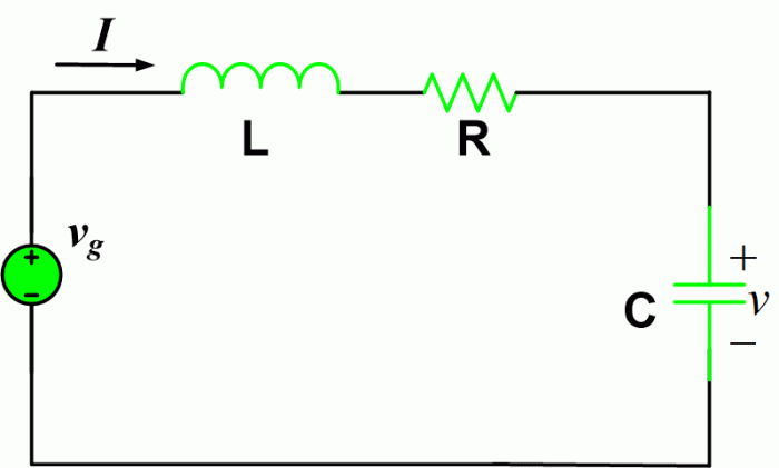
Resonance frequency in an RLC circuit is the frequency at which the inductive reactance and capacitive reactance cancel each other out, resulting in a purely resistive circuit. At this frequency, the circuit exhibits maximum energy transfer and minimum impedance.
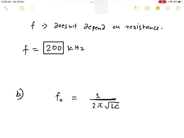
The resonance frequency is determined by the inductance (L), capacitance (C), and resistance (R) of the circuit, and is given by the formula:
fr= 1 / (2π√LC)
Factors Affecting Resonance Frequency
- Inductance (L):Higher inductance increases the inductive reactance, shifting the resonance frequency to a lower value.
- Capacitance (C):Higher capacitance decreases the capacitive reactance, shifting the resonance frequency to a higher value.
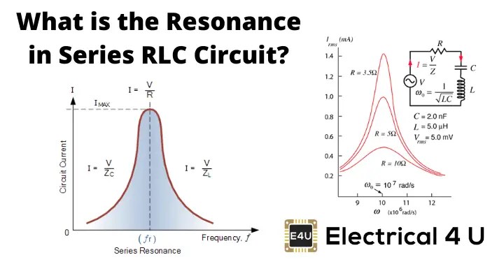
- Resistance (R):Resistance does not directly affect the resonance frequency, but it influences the bandwidth and quality factor of the circuit.
Circuit Behavior at Resonance

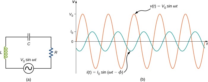
At resonance, the voltage and current in an RLC circuit are in phase, meaning they reach their maximum and minimum values at the same time. The impedance of the circuit is at its minimum, and the power factor is at its maximum.
Phase Shift
Below resonance frequency, the current lags the voltage by an angle φ. Above resonance frequency, the voltage lags the current by an angle φ.
Impedance, A series rlc circuit has a 200 khz resonance frequency
At resonance, the impedance of the circuit is purely resistive, and is given by:
Z = R
Power Factor
At resonance, the power factor is at its maximum value of 1, indicating that the circuit is purely resistive and all of the power is being dissipated as heat.
Applications of Resonance

Resonance is used in a wide variety of electronic circuits, including:
Filters
Resonant circuits can be used to filter out specific frequencies from a signal. For example, a low-pass filter uses a resonant circuit to block high frequencies, while a high-pass filter uses a resonant circuit to block low frequencies.
Oscillators
Resonant circuits can be used to generate oscillations at a specific frequency. For example, a crystal oscillator uses a resonant circuit to generate a precise frequency for use in clocks and other electronic devices.
Analysis Methods

There are several methods for analyzing RLC circuits at resonance, including:
Phasor Diagrams
Phasor diagrams are a graphical representation of the voltage and current in an RLC circuit. They can be used to determine the phase shift between voltage and current, as well as the impedance and power factor of the circuit.
Complex Impedance
Complex impedance is a mathematical representation of the impedance of an RLC circuit. It can be used to analyze the circuit’s behavior at any frequency.
Circuit Design Considerations
When designing RLC circuits that operate at resonance, it is important to consider the following factors:
Component Selection
The inductance, capacitance, and resistance of the circuit must be carefully selected to achieve the desired resonance frequency and bandwidth.
Layout
The layout of the circuit can affect the resonance frequency and bandwidth. For example, stray capacitance and inductance can alter the circuit’s behavior.
Avoiding Unwanted Resonances
It is important to avoid unwanted resonances in RLC circuits, as they can cause instability and other problems. This can be done by using damping resistors or by careful layout.
FAQ Explained
What is the significance of resonance frequency in RLC circuits?
Resonance frequency is a crucial parameter that determines the circuit’s ability to amplify specific frequencies, making it essential for applications such as filters and oscillators.
How does the inductance, capacitance, and resistance affect the resonance frequency?
Inductance, capacitance, and resistance are inversely related to the resonance frequency, meaning that changes in these components will alter the frequency at which the circuit resonates.
What are the advantages of using phasor diagrams and complex impedance in analyzing RLC circuits?
Phasor diagrams and complex impedance provide graphical and mathematical tools that simplify the analysis of RLC circuits, allowing for a deeper understanding of their behavior.